Decorations
path-shaped-grid
This script produces a polygonal grid path with various shapes, where all segments of the grid correspond to individual path strokes.
The options are:
Shape
The shape of the polygon: hexagon, rhombus, triangle, square, diamond.
Size
The size of the reference side of the polygon (the one which is vertical or horizontal) or, for diamonds, the width or height.
Aspect ratio
The aspect ratio of the polygon. "0" is a regular polygon, positive numbers increase the size perpendicularly to the reference side, negative numbers reduce it.
Direction
For hexagon, rhombus and triangle, determines if the polygons will have a vertical or a horizontal side. For squares and diamonds, this only changes which direction is the reference.
Anchor X, Anchor Y
The coordinates of one vertex in the grid. In other words, it insures that the grid will have one vertex at that point.
Partial start, Partial end
The position of the actual start and end of the stroke on the side of the polygon. Values 0 and 100 create a stroke that completely covers the side between the two vertices. Values can go as low as -100 and as high as 200 to extend the stroke beyond the polygon side.
Round to integer pixels
If yes the shape is slightly distorted to have integer pixel dimensions. This produces perfectly tilable patterns (by croppig the resulting image to a rectangle with the size indicated in the path name).
Single path
If yes, one single path is produced. If no, a separate path is produced for each side direction.
Usage notes
One can produce very complex patterns by running the script several times using slightly different settings (mosty Anchor and Partial)
and merging the results.Using the path-to-shape script to produce circles from the segments produces even more complex (but still completely regular) patterns.
slinky
Slinky is mostly obsolete. For most purposes it can be replaced by path-waves
It is kept here because there is some functionality that is missing in path-waves.
Slinky creates a sinusoidal path that follows an existing path. The zigs and the zags can be put in two different paths, that, if stroked in two different layers, will create the perspective of a coil around something in a middle layer.
The options are:
Pitch
The lengh of a full period of the sine curve, in pixels.
Width
The width of the sinewave, in pixels (that will extend for one half on each side of the path)
Phase shift
The phase of the sine wave at the beginning of a stroke, in degrees. It is mostly useful when using Slinky several times on the same path, to offset the sine curves.
Split top and bottom
If 'yes', Slinky will produce two paths, one for the zigs, and one for the zags.
If 'no', will produce one single path.
Adjust pitch to close path
If 'yes', the pitch value entered will be slightly altered on each stroke to make it an exact
submultiple of the length of the stroke to ensure proper closure of the sine wave.
This option is active only on 'closed' strokes. If the path is not split, the stroke is additionaly "closed".
Usage notes
Sharp turns in paths are currently poorly handled
Acknowledgments
This plugin is the result of some intense team work that should be given appropriate recognition, so:
- Thanks to 2-ton@gimpchat for suggesting the catchy name.
- Thanks to the cheering crowd at GimpChat for the rain dances, even if there is indication that they have overdone it a bit, or have very strong powers.
path-waves
path-waves creates a wave that follows an existing path. The wave can have several
shapes:
- square
- triangle
- sine: the intersection with the path is at an angle depending on the pitch/width ratio
- ellipse: the intersection with the path is perpendicular.
- circle: the intersection with the path is perpendicular, and the circular shape is enforced (the width parameter is ignored)
Of course, the names of the shapes refers to the shapes obtained from a straight path; the curvature of the path can severely distort them in some cases.
The zigs and the zags can be put in two different paths, that, if stroked in two different layers, can create perspective effects (with the sine wave: of a coil around something in a middle layer).
The options are:
Wavelength
The length of a full period of the wave, in pixels. The pitch value entered will usually be slightly altered on each stroke to make it an exact submultiple of the length of the stroke to ensure proper closure of the wave.
Amplitude
The amplitude of the wave, in pixels (on each side of the path, the wave will therefore be twice as wide in most cases)
Wavelength shift
The phase of the wave at the beginning of a stroke.
With None, the wave starts on the path. On closed strokes, this doesn't make much difference, but this allows to control the relative
position of several waves produced on the same stroke.
Asymmetry
An asymmetry factor whose effect depends on the wave shape:
- square: this changes the "duty cycle" of the wave
- triangle: this changes the symmetrical triangle into a sawtooth
- sine: the effect is similar to the triangle
- ellipse: the effect is similar to the sine.
- circle: this determines the relative side of the half-circles on either side of the path.
Split top and bottom
If 'yes', the script will produce two paths, one for the zigs, and one for the zags.
If 'no', it will produce one single path.
Usage notes
Sharp turns in reference paths will cause important distortions.
path-arrow-heads
This script adds arrowheads at the end of open path strokes.
Typical usage
Create the arrow lines with the Paths tool

Run the script to create another path with open arrow heads

Merge the two paths and stroke the result

Or run the script to create another path with closed arrow heads

Create a selection from that path and fill it, and stroke path with the arrow lines

Options
The options are:
Size
The length of the arrow wings.
Angle
The angle of the arrow wings with the axis of the arrow head. The angle between the arrow wings is therefore twice this angle.
Ends
The ends of the strokes that should receive an arrow head. Some path transformations
can swap strokes end to end and result in an arrow head that doesn't show up where expected.
See reverse-strokes in the Tools section to fix the bad cases.
Close
If 'yes', the arrow head will be a triangle usable for selection and fill.
Axis
'tangent' sets the axis of the arrow head to the exact tangent to the curve on the ending point
of the stroke, while 'best fit' adjusts this axis to make the arrow head look a bit more natural.
Usage notes
For best results, keep the length of the arrow wings under a third of the curve radius of the stroke (in other words, don't expect miracles on sharp turns ended by an arrowhead)
neon-path
This script produces a "neon tube" rendering from a path. The rendering is produced on a new layer, and, if requested, a secondary layer is produced to emulate glow or reflection. There is one tube per stroke in the path.
The neon tube colors are taken from the current gradient. The darker part of the tube is the leftmost color of the gradient, and the lightest part the rightmost. This gradient can be the standard foreground-to-background gradient (in which case the colors used will the current foreground and background colors), or specific gradients.
There are two options:
Width
The width of the neon tube produced
Relative width of glow
When not 0, a secondary layer is produced with a larger and blurry image of the tube, that can be used as a glow effect or as a reflection. The layer is preset to 50% transparency but depending on the effect sought, this can be changed or the layer can be blurred further. To emulate a reflection on some background plane, this layer can also be shifted.
Usage notes
For a more realistic look:
- A good starting point for the colors is to select them using HSV instead of RGB: pick a rather luminous color (V>80), fully saturated (S=100) for the darker color, and the same hue (H value), desaturated (S around 50) and more luminous (V>90) for the lighter part of the tube.
- Paths obtained from text are usually "outline" paths and not "stroke" paths, while real neon signs are usually of the "stroke" kind ( See the path FAQ for more information.). Furthermore, when using stroke fonts, the path generated can be amended by opening closed loops (as in "O"), and avoiding junctions and intersections (as in "A", "T"...)
Another completely different usage of this script is to approximate a gradient of a given width, directed by the path.
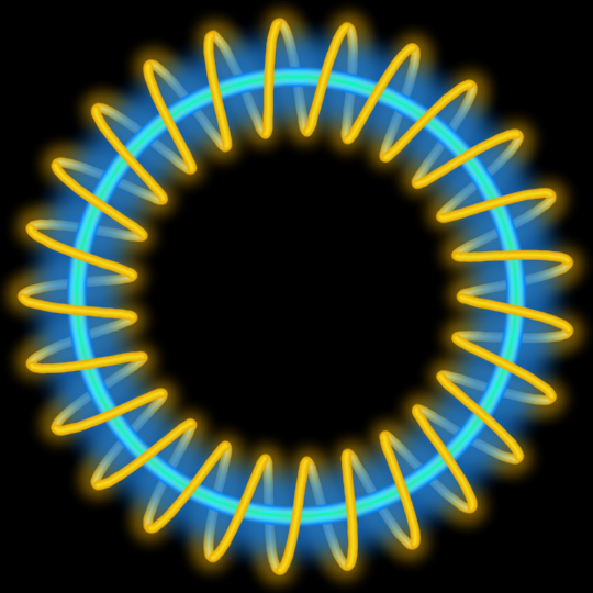
slinky and neon-path team work
Just showing off...